The Pedal Gee Bee
The ongoing saga of the construction of a pedal powered Gee Bee R2 replica for my kids.
Thursday, October 13, 2005
Gear Assembly
After sanding the wheel cover opening so that the gear sat correctly, I used urethane glue and some VERY thin pine shims to glue it in. Basically I got the gear in up to the line, and used the glue covered shims to center it into the opening. Careful insertion of the wedged shape shims allowed for fine adjustment, making sure that not only is the gear centered but perpendicular to the cover. Once the glue had set, I snapped off the exposed parts of the shims. I’ll follow up tomorrow night with either more glue or fiberglass resin to fill the remaining gap around each gear. This last step will be important to the rigidity of the final assembly since this assembly will be experiencing a lot of stress as the craft is being used. By filling in all of the gaps, the gear will be EXTREEMLY stiff, which is exactly what we’re looking for.
Pictures soon….
Tuesday, October 11, 2005
Rear fuselage covers installed
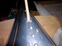
At the very beginning, I realized that in order for the lower bend in the cover to sit correctly at the top edge of the fuselage, there would be a large overhang at the headrest, and an overly large gap at the rudder. Unlike the windshield, there was no way to re-bend this piece, so I was stuck. Determined to make the best of it I installed the first two screws at the headrest counter-bend and a single one at the rear in the rudder. With the cover now securely in place, I examined how the top of the cover would need to get bent down and secured to the dowels in the rudder. Since this is were the other side’s cover would overlap, you need to bend the cover enough to sink down below the other side, yet not so severely that it breaks the smooth curve coming up from this side.
Once the first side was in place I moved on to the other. Again, a large overlap at the headrest, and a gap at the tail. Oh well, at least the gaps are symmetrical. The second cover attaches at the top by screwing through both covers directly down into the spine of the rudder. This allows the exposed screws to be placed down the centerline of the craft. With a little persuasion and help from Jen (I swear some parts of this project require 5 hands at once), I managed to drill the holes and install the screws. With all the minor defects I learned to live with throughout this project I was ready to accept a lot less than perfection right here. I was pleasantly surprised to see that the junction at the top of the covers, the headrest, and the rudder turned out great.
I scribed the lines where I would need to cut off the headrest overhang and excess overlap, and removed the covers. I cut the excess with my aviation shears (a rather apt name for a general tool) and de-burred with a number of files. Reinstalled the covers, and called it a night.


