The Pedal Gee Bee
The ongoing saga of the construction of a pedal powered Gee Bee R2 replica for my kids.
Thursday, October 13, 2005
Gear Assembly
After sanding the wheel cover opening so that the gear sat correctly, I used urethane glue and some VERY thin pine shims to glue it in. Basically I got the gear in up to the line, and used the glue covered shims to center it into the opening. Careful insertion of the wedged shape shims allowed for fine adjustment, making sure that not only is the gear centered but perpendicular to the cover. Once the glue had set, I snapped off the exposed parts of the shims. I’ll follow up tomorrow night with either more glue or fiberglass resin to fill the remaining gap around each gear. This last step will be important to the rigidity of the final assembly since this assembly will be experiencing a lot of stress as the craft is being used. By filling in all of the gaps, the gear will be EXTREEMLY stiff, which is exactly what we’re looking for.
Pictures soon….
Tuesday, October 11, 2005
Rear fuselage covers installed
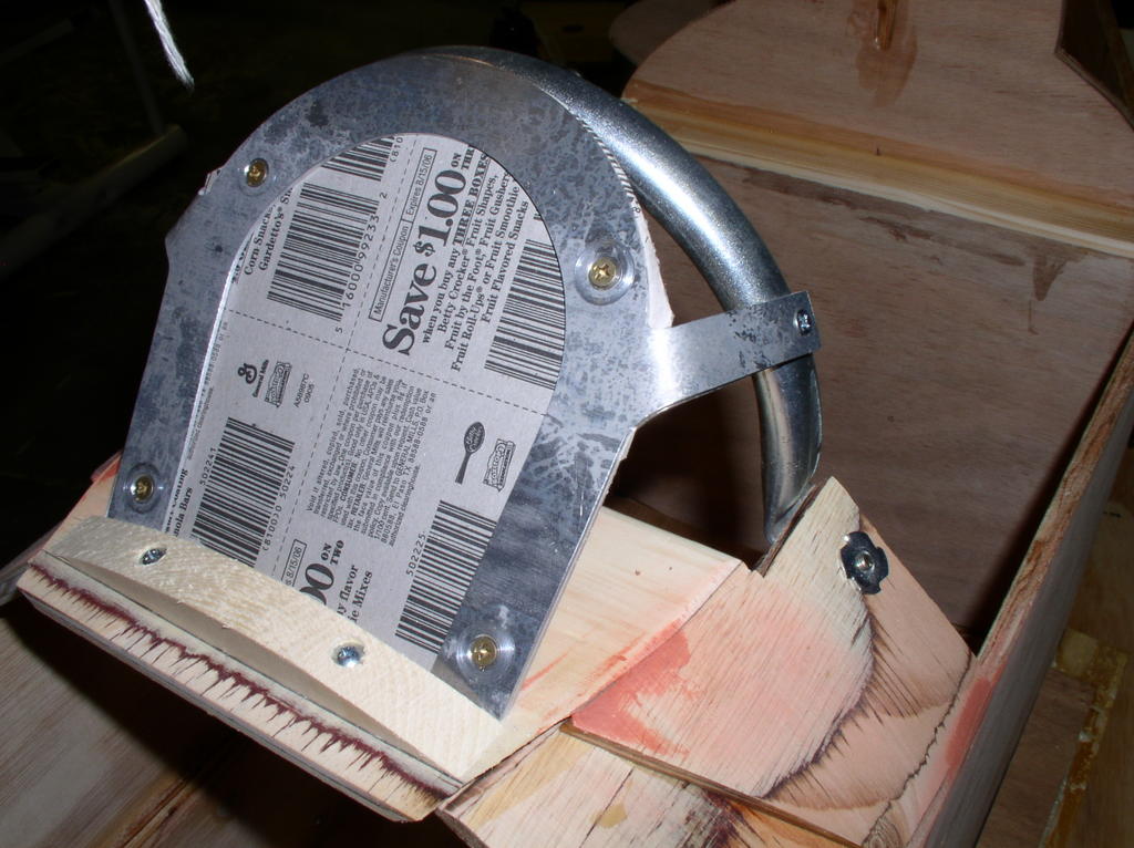
At the very beginning, I realized that in order for the lower bend in the cover to sit correctly at the top edge of the fuselage, there would be a large overhang at the headrest, and an overly large gap at the rudder. Unlike the windshield, there was no way to re-bend this piece, so I was stuck. Determined to make the best of it I installed the first two screws at the headrest counter-bend and a single one at the rear in the rudder. With the cover now securely in place, I examined how the top of the cover would need to get bent down and secured to the dowels in the rudder. Since this is were the other side’s cover would overlap, you need to bend the cover enough to sink down below the other side, yet not so severely that it breaks the smooth curve coming up from this side.
Once the first side was in place I moved on to the other. Again, a large overlap at the headrest, and a gap at the tail. Oh well, at least the gaps are symmetrical. The second cover attaches at the top by screwing through both covers directly down into the spine of the rudder. This allows the exposed screws to be placed down the centerline of the craft. With a little persuasion and help from Jen (I swear some parts of this project require 5 hands at once), I managed to drill the holes and install the screws. With all the minor defects I learned to live with throughout this project I was ready to accept a lot less than perfection right here. I was pleasantly surprised to see that the junction at the top of the covers, the headrest, and the rudder turned out great.
I scribed the lines where I would need to cut off the headrest overhang and excess overlap, and removed the covers. I cut the excess with my aviation shears (a rather apt name for a general tool) and de-burred with a number of files. Reinstalled the covers, and called it a night.


Tuesday, September 27, 2005
Front fuselage cover installed
Time for some sheet metal work! The first thing I noticed was that the cutout for the windshield frame in the front cover didn’t allow the cover to be installed far enough back on the craft. Unmodified, it would end about a half inch short of the cockpit edge. So with much trepidation I began to drill, snip and file the cover into the shape I needed. Along the way I noticed that if I would use a taller rear cowl former, the entire piece would fit better. So I cut a new one on the band saw and installed it. Once I was comfortable with the fit, I marked were the cover meets the fuselage side. Here, I needed to (as per this instructions) bend down the cover to approximately 40 degrees so that the cover can transition from the rounded top of the fuselage to the straight side. Since I’m not in the gutter or siding business, I didn’t have access to a sheet metal break. So I improvised. I clamped the cover down to my workbench so that the line where the bend should be was directly over the edge of my workbench top. Then, proceeding VERY carefully, I tapped lightly from one side to the other with my rubber mallet. After about four or five passes I achieved a nice, sharp bend that matched perfectly to the fuselage.
I then cut out the notches where the wires will pass out the fuselage towards the wing. The dremel with an abrasive cutting disk worked the best. A little filing to de-burr, and the cover was re-installed. WOO HOO!!


Thursday, September 22, 2005
Windsheild Trim Installed
Once the former was in place, I put a piece of thin cardboard between the windsheild trim halves as instructed. This piece simulates the width of the actual plastic windsheild film that will be installed at a later time. The trick was sanding and placing the trim centered on 1. the panel top; 2. the windshield frame; and 3. the cowl when viewed head-on. Upon final inspection it's centered on 1 and 2, but lookis off in relation to 3. Oh well, nothing I can do about it at this point.


Windsheild Frame Mounted
Mounted the windsheild frame tonight. It was fairly straightforward, since I made sure that the panel assembly was square to the rest of the fuselage. After clamping the frame securely to the fuse, I marked the centers of all the holes to be drilled. I removed the frame, and drilled the 3/16ths holes in the fuselage and the 1/4 inch holes through the panel sides. It was then a simple matter of using the supplied (you did get the harware kit like I told you to...right?) flathead screws and hex head bolts with stop nuts to premanently mount the frame.
Some notes here:
- Make sure when you're clamping the frame in, before marking the holes, that the frame is centered in the panel opening
- Make sure that the frame is perpendicular to the fuselage sides. Otherwise your windseild will be tilting forward or backward. Not a big deal but square always looks better.


Friday, September 09, 2005
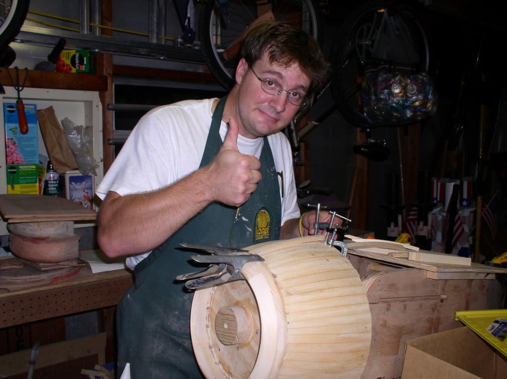
Cowl Completed!!!!!!!!!
I finally completed the cowl!!!!! This is so cool!!!
I’ve run my hands over it so many times, just to prove to myself that I really built it. I just get a kick out of knowing that I built an object that curves in all three dimensions from a straight 1x8 piece of pine.
It still needs to be filled and sanded. I’ll need to use some Bondo to hide the transition from the cowl body to the noseplate. It’s relatively close, but if you look perpendicular to the cowl you can see that the two curves are distinct. It should be a smooth compound curve from the firewall to leading edge. After that I’ll have to trim, fill, and sand the aft edge where the cowl ribs attach to the firewall. The final step will be to sand the heck out of it so that it’s ready for priming. There’s certainly PLENTY of work left before it could get painted, but to me, the project has passed its second major milestone.


Tuesday, September 06, 2005
More Ribs and Wheel Covers

Time spent: 2 hours (evening)
Glued in 6 more cowl ribs. I would have done more but both sides need an alignment adjustment rib, and I didn’t feel like hauling out the table saw tonight. I wish this process was faster, but every time I run my hand over the increasingly rounded cowl I feel a sense of accomplishment.

I finished shaping the second wheel cover using the disk sander/belt sander/hand sanding technique I described in a previous post. This time the process was a little faster, but I paid for it. The disk sander sensed my haste, and penalized me ¼ of the fingernail on my right index finger. I was listening to the Brewer game, rough-rounding the cover to shape, when my index finger got too close and caught between the wood and the disk. There was no blood drawn, since I was quick on the recoil and the disk speed partially cauterized the abrasion. However, it stings like hell, feeling like someone trimmed my fingernail WAY too far back.
Friday, August 26, 2005
Nose Ring Sanded to Shape
I sanded the nose ring to shape tonight. I'm extreeemly pleased with the results. I attached the nose ring on a 1/2 inch threaded rod arbor mounted in my drill press. Then, turning the assembly around 500 RPM, I used a combination of the belt sander and hand sanding to get it into the final shape. We'll see how well this matches the final cowl shape. I'm sure I'll need to do some filling and sanding but DAMN! this thing looks good.


Previous Posts
- Gear Assembly
- Rear fuselage covers installed
- Front fuselage cover installed
- Windsheild Trim Installed
- Windsheild Frame Mounted
- Cowl Completed!!!!!!!!!
- More Ribs and Wheel Covers
- Nose Ring Sanded to Shape
- Nose Ring Turned to Size
- Cowl rib band saw jig built
Post Archives
Additional Links
- Aviation Products Inc.
- Makita
- Porter Cable
- Black and Decker
- CMT Router Bits
- Ryobi
- Delta
- Miller Brewing
My Other Blogs
![]()
